This is a place holder page for my latest Cisco ACI/HPE Synergy InterOp decks.
Latest Cisco ACI/HPE Synergy Virtual Connect InterOp Presentation
Reply
This is a place holder page for my latest Cisco ACI/HPE Synergy InterOp decks.
I’d like to share one Synergy OneView CLI I have been working on.
https://hjma29.github.io/ovcli/
The tool is about 10M bytes and can be used on windows/Linux/MAC platform.
If you are IT admin and just want to run the tool without worrying about install any programming dependencies, you can download .exe file from the web directly. Another option is to run the tool with the docker image format
User Tutorials:
1. How to use ovcli tool https://youtu.be/BveIKt9–4Y
2. How to use ovcli docker image https://youtu.be/dP6sHnvYaVI
In any case, if you know Go programming language and wants to compile from the source, you can do “go get” from github repo directly.
The CLI tool intends to complement the current OneView GUI, Powershell cmdlets and other devops tools like Python/Ansible libraries.
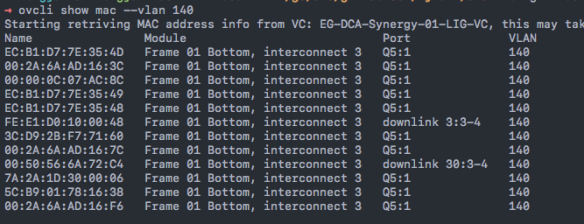
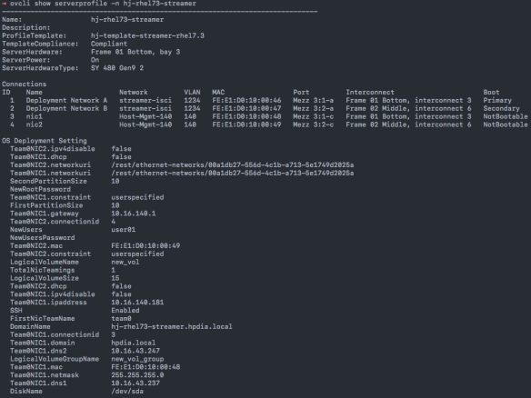
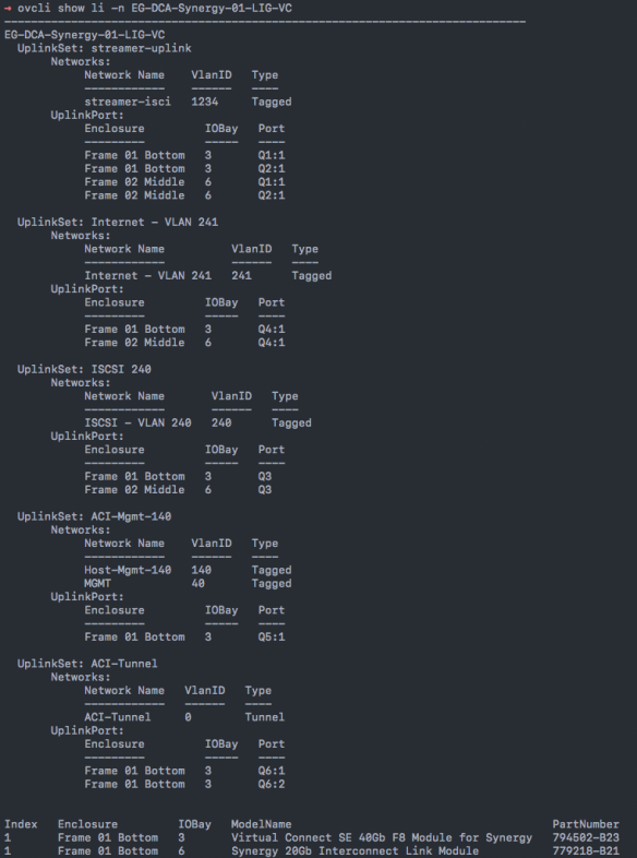
Some of the examples are shown below like show mac, show server profile, show logical interconnect. You can do other commands like create/delete/edit Synergy resources.
When connecting Cisco ACI fabric with HPE blade servers through HPE Virtual Connect Modules, users should pay additional attention when working with VC tunnel networks. Both ACI and VC tunnel mode has some unique internal traffic forwarding mechanism when comparing with traditional L2 MAC forwarding method.
This blog intends to highlight one scenario users may see unexpected traffic behavior when connecting ACI with VC tunnel mode. Some potential design alternatives to resolve the issue are then discussed.
Virtual Connect tunnel network has the benefit of scalability and simplicity of management. Instead of configuring individual vlans matching upstream switch and downlink blade servers, a single Virtual Connect network can transit up to 4K vlans transparently. Users only need to configure vlans at upstream switch and blade servers OS/hypervisor level.
When using Virtual Connect tunnel networks, internally VC maintains a consolidated MAC forwarding table for the defined VC internal tunnel network instead of separated MAC table per user VLAN defined at switch and server side.
This unique operation characteristics of VC tunnel network needs to be taken into consideration when working with ACI Fabric. ACI uses Bridge Domain(BD) as layer 2 broadcast boundary and each BD can include multiple End Point Groups(EPG). At access layer, users can bind encapsulation vlan to the desired EPG to carry user traffic. As you can see, in some ACI design scenarios, flooding can cross different user vlans(EPGs) when the EPGs are in the same BD.
The following diagram shows one of the problematic scenarios of connecting VC tunnel network and ACI .
(Please note: The diagram only demos one use case to see this interop issue. Other cases may exist with the same issue so the key is to understand the nature of the problem.)

In the above topology, Virtual Connect has one single tunnel network defined and uses one uplink to connect with ACI leaf node. Over this link, two user vlans are carried through, vlan 160 and vlan 161. On ACI side, vlan-160 is used as encap-vlan for EPG Mgmt and vlan-161 is used as encap-vlan for EGP vmotion.
ACI BD domain is set as flooding mode as blade servers’ gateway are outside ACI cloud.
In this setup, user will have connectivity issue for the blade servers. This is how the problem will arise.
1) The blade server sends one ARP broadcast request over vlan 160 network. The ARP packet will travel through VC tunnel network. VC will record blade server source MAC address learned from the server downlink and forward the packet out to its local uplink to ACI. so far so good.
2) ACI fabric will see the ARP broadcast packet coming in on access port vlan 160 and will map it into EPG Mgmt. Because BD is set to flood ARP packets. The packet will be flooded inside the bridge domain and will be in turn to all ports under EPG vMotion as the two EPGs are in the same BD.
The following capture was from ACI fabric access SPAN session capture the access port EGRESS direction. We saw the same ARP broadcast packet flooded out of the port(in EGP vMotion)
3) The same ARP broadcast packet will come back over the same uplink. VC will see the original blade server source MAC address from this uplink. At this point, VC will have the same MAC learned from both downlink server port and the uplink port within its single tunnel network MAC forwarding table. Remember VC tunnel mode will consolidate MAC table instead of maintaining per-vlan MAC table. This will in turn cause traffic interruption for this server.
There are several resolutions to the above scenario.
1) Set up ACI fabric EPG and BD as one to one mapping to simulate traditional layer 2 flooding behavior. So the flooding traffic in one EPG will not be able to reach other EPGs.
2) Use VC mapped mode networks. VC mapped mode networks are mapping to individual user vlans so will not have this conflicting MAC learning issue due to the fact that VC will maintain separate MAC forwarding table separation per user VLAN.
3) There is one promising ACI option. Although it doesn’t resolve this issue currently, I hope the feature can be enhanced in the future.
ACI release 1.1(1j) introduced the new option for BD flooding behavior called “Flood in Encapsulation”. This is to contain the flooding traffic inside the BD to only flood the traffic within the same EGP encapsulation vlan. This is a a promising solution as EPG Mgmt flooding traffic will not reach EPG vMotion with this option turned on even if these two EPGs share the same BD.
However, my test shows that even after setting this option, I still see flooding across EPG encap-vlans. Cisco ACI Fundamental also specifically pointed out the unsupported protocol for this option. This include ARP traffic, many common routing protocol like OSPF/BGP/EIGRP, multicast protocols like PIM/IGMP. So until this option can support ARP packets, it won’t be a viable solution for this case.
For readers want to dig deeper into VC tunnel mode MAC table, you can view VC internal tunnel network MAC forwarding table by the following method.
If VC is managed by HPE OneView software, you can make RestAPI call to OneView appliance like the following captures. You can see when the problem was seen, the blade server MAC address was learned from uplink LAG 25, which is VC module port X7. In working scenario, the same MAC address should be learned from server downlink like “downlink 3-a”.
HP OneView PowerShell cmdlet “show-HPOVLogicalInterconnectMacTable” can also retrieve VC MAC table.
The capture below shows incorrect MAC address entry after VC received the original packet from uplink. You can see LAG(Link Aggregation Group) 25 is on uplink X7.


The capture below shows the correct MAC address entry from server downlink “3-a”(Server bay 3, first flexNIC inside the physical link) before the issue.
If Virtual connect is managed by classic Virtual Connect Manager, you can use “show interconnect-mac-table” to retrieve MAC table information. The following capture just gives you an idea how the output looks like. It’s not for the scenario and configuration described above.
The following capture shows blade server connectivity issue we just discussed.
For HP Proliant server customers using Cisco B22 FEX modules, this presentation can help you with understanding how to design and configure B22 for ethernet and FCOE connectivity. The presentation can be downloaded here.

It’s common that server admins need to set up PXE and FCOE configuration for HP Proliant servers. For HP blade server with Virtual Connect modules, users can configure all PXE and FCOE settings in either OneView or classic Virtual Connect Manager GUI.
However, some customers may need to use other switches other than HP Virtual Connect for HP Proliant server network connectivity. This includes Proliant blade servers using Cisco B22 FEX module or other blade switches as well as Proliant rack servers. Meanwhile, many HP Proliant servers these days are shipped with Emulex CNAs as LOM or FlexLOM.
It can be tricky to set up PXE and FCOE without Virtual Connect profile concept because users need to enter server RBSU and Emulex ROM to configure relevant settings.
This presentation is to help users with server RBSU and Emulex ROM PXE and FCOE configuration. At the end of the presentation, there is also a section of Emulex BFS booting messages where you can see the common booting errors and related causes. This actually will even help you to troubleshoot when you are using Virtual Connect module.
Hope it helps your deployment. The presentation can be downloaded here.

HP’s new infrastructure management OneView is announced today. This is a very big announcement for HP.
It’s the next-generation HP management software to combine management of HP Proliant blade and rack servers. In near future, it’ll also provide HP storage(3PAR) and networking management.
In version 1.0, here are some key technical facts
You can watch quick product demos and OneView marketing page here. There are 4 good technical demos after you click “Get An HP OneView Demo”.
Also, this is a video link showing how OneView is different than Cisco UCS in the way it operates.
One of VC 4.01 features is an option to let users to configure LACP timeout to Long Timeout(30sec instead of default short timeout 1 sec). Sometimes data center switches would like their LACP neighbors to use Long Timeout and this feature will meet such requirement. One of the use cases is to help Cisco Nexus customers who wish to perform ISSU. One of ISSU requirements is all LACP timers need to be set as Long Timeout.
Before VC4.01, Nexus customers will see this on Nexus side when connecting with Virtual Connect.
N5K-1# show lldp neigh
Capability codes:
(R) Router, (B) Bridge, (T) Telephone, (C) DOCSIS Cable Device
WLAN Access Point, (P) Repeater, (S) Station, (O) Other
Device ID Local Intf Hold-time Capability Port ID
ProCurveSwitch2900-24Gmgmt0 120 BR 14
N5K-2 Eth1/1 120 B Eth1/1
N5K-2 Eth1/2 120 B Eth1/2
Enc-FF-VC-1 SERIAL NO:TW201300H8 BAY:1Eth1/3 120 X1
Enc-FF-VC-1 SERIAL NO:TW201300H8 BAY:1Eth1/4 120 X2N5K-1# show lacp interface e1/3 Interface Ethernet1/3 is up Channel group is 1 port channel is Po1
<snip>
Neighbor: 0x11 MAC Address= 0-24-81-f7-c6-f7 System Identifier=0x1,0-24-81-f7-c6-f7 Port Identifier=0x1,0x11 Operational key=2 LACP_Activity=active LACP_Timeout=short Timeout (1s) Synchronization=IN_SYNC Collecting=true Distributing=true Partner Admin State=(Ac-0:To-1:Ag-0:Sy-0:Co-0:Di-0:De-0:Ex-0) Partner Oper State=(Ac-1:To-1:Ag-1:Sy-1:Co-1:Di-1:De-0:Ex-0) N5K-1#
N5K-1# show lacp issu-impact
For ISSU to Proceed, Check the following:
1. The port-channel member port should be in a steady state.
2. Check if any of the port-channel member has fast timer enabled from the remote peer
.
The following ports are not ISSU ready
Eth1/3 , Eth1/4 ,
With 4.01, VC has the long timeout option now.

and this is how Nexus end should look like after VC set his end to do LACP Long Timeout.
N5K-1# show lacp interface e1/3 <snip> Neighbor: 0x11 MAC Address= 0-24-81-f7-c6-f7 System Identifier=0x1,0-24-81-f7-c6-f7 Port Identifier=0x1,0x11 Operational key=2 LACP_Activity=active LACP_Timeout=Long Timeout (30s) Synchronization=IN_SYNC Collecting=true Distributing=true Partner Admin State=(Ac-0:To-1:Ag-0:Sy-0:Co-0:Di-0:De-0:Ex-0) Partner Oper State=(Ac-1:To-0:Ag-1:Sy-1:Co-1:Di-1:De-0:Ex-0)
N5K-1# show lacp issu-impact
For ISSU to Proceed, Check the following:
1. The port-channel member port should be in a steady state.
2. Check if any of the port-channel member has fast timer enabled from the remote peer
.
All the port are ISSU ready
N5K-1#
Please Note:
1. If you still see Nexus show VC neighbor as “Short_Timeout” even after you set VC as Long, try to set VC back to Short and apply and then try to set VC back to Long again and apply to see if it can negotiate successfully.
2. Resetting LACP timer might have short traffic interruption for your application. I lost one ping during LACP timer changes on VC side while other times I didn’t lose any pings when doing the same LACP timer changes.
VC3.70 was just released and it’s a feature release, which means that it includes more features compared with VC3.60 and VC3.51 where both of them are primarily bug-fix releases with VC3.51 starts to support Gen8 server(BL460Gen8).
One of the major features in VC3.70 is Virtual Connect 3PAR storage array direct attach. Now you can direct attach 3PAR storage array directly with VC FlexFabric module without any SAN switching layer. I created a presentation to show how to config 3PAR and VC FlexFabric for this feature. Please download the deck Here.
Another feature in VC3.70 is to support newly release Virtual Connect Flex-10/10D module. Comparing this module with original Flex-10, this module provides more uplink ports(10) and also 4 internal 10G stack links. I don’t see you’ll use too much of internal 40G stacking bandwidth, especially if you use VC Active/Active design, where your user traffic will go directly from downlink to uplink and vice versa without using stacking link. The best thing is that you can now use all 10 uplink ports without worrying about original Flex-10 X7/X8 shared stacking link. You can check the module spec from the quick link in my VC bookmark page at the top of the web page.
Also, Flex-10/10D module is planned to provide FCOE uplink(Not FC uplink) and FCOE downlink in the future.
For more information on this new module and 3.70 new features, please check my Virtual Connect Technical Overview Presentation. I just updated it with the new contents.
One of commonly asked questions is how to cable up Virtual Connect Flexfabric modules to LAN and SAN switches. It’s quite simple after you understand the module but a little confusing when you are first learning it. I created a short powerpoint deck trying to show users very common used VC cabling in real-world scenario.
You can download the deck here.

The white paper is good for anyone new to VCEM and want to quickly go through docs for look and feel of the VCEM. It’s also good for anyone wants to set up a quick POC on VCEM.
http://h20000.www2.hp.com/bc/docs/support/SupportManual/c03115781/c03115781.pdf
